
6j1 Tube Preamp
I was browsing online for a soldering project for my oldest son for Christmas, when I came across this 6J1 Tube Preamp kit. It is intended for RCA, but I was hoping to play with adding 1/4" jacks to run my guitar through it.


Above we can see the capacitors soldered in place

At this point I wasn't sure what I should use for a case. I just had to mount it to something, so I found a piece of aluminum that had some holes in it already and formed it to the shape I needed.

Once getting it to this point, I decided to draft it in SolidWorks to elaborate more on it.


Prototyping off a scrape piece of aluminum has come a long way and designing all components in solidworks has allowed me elaborate more on the idea.


The end result is truely pleasing. During the designing process, considerations were made to make it something easily reproducible with a total of eight printed parts, screws available from computers and a transformer with a seemingly common footprint and bolt pattern.


Over all it was a very fun project and the amp turned out awesome. The price point of preamps can be found for around 10 dollars and have so many various applications for projects like this.

Want the files? Email me!
What is a preamp?
A preamp is an electrical device that takes a weak signal and amplifies it, making a weak signal stronger for further processing. Tube amps have always been said to have a warmer sound over solid-state.
The Build
The kit comes with all the pieces tossed in a bag with no schematic, however; the board is clearly marked and all you really need to do is sort it all and organize your components. You can use a page like All About Circuit's resistor calculator to determine the Ohms by colour code bands, or you can switch your multimeter to Ohms and test manually - which is typically quicker.
Note: The board lists the 2.2k and 4.7k as "2k2" and "4k7"
I tend start with all resistors as they are generally the lowest profiled components to be soldered - and while are not directional in anyway, I try to keep them in the same orientation across the board for quick refferencing if needing to troubleshoot later.
It's important to take note that the transistors are different pairs B647 - D667, and the locations respectively.
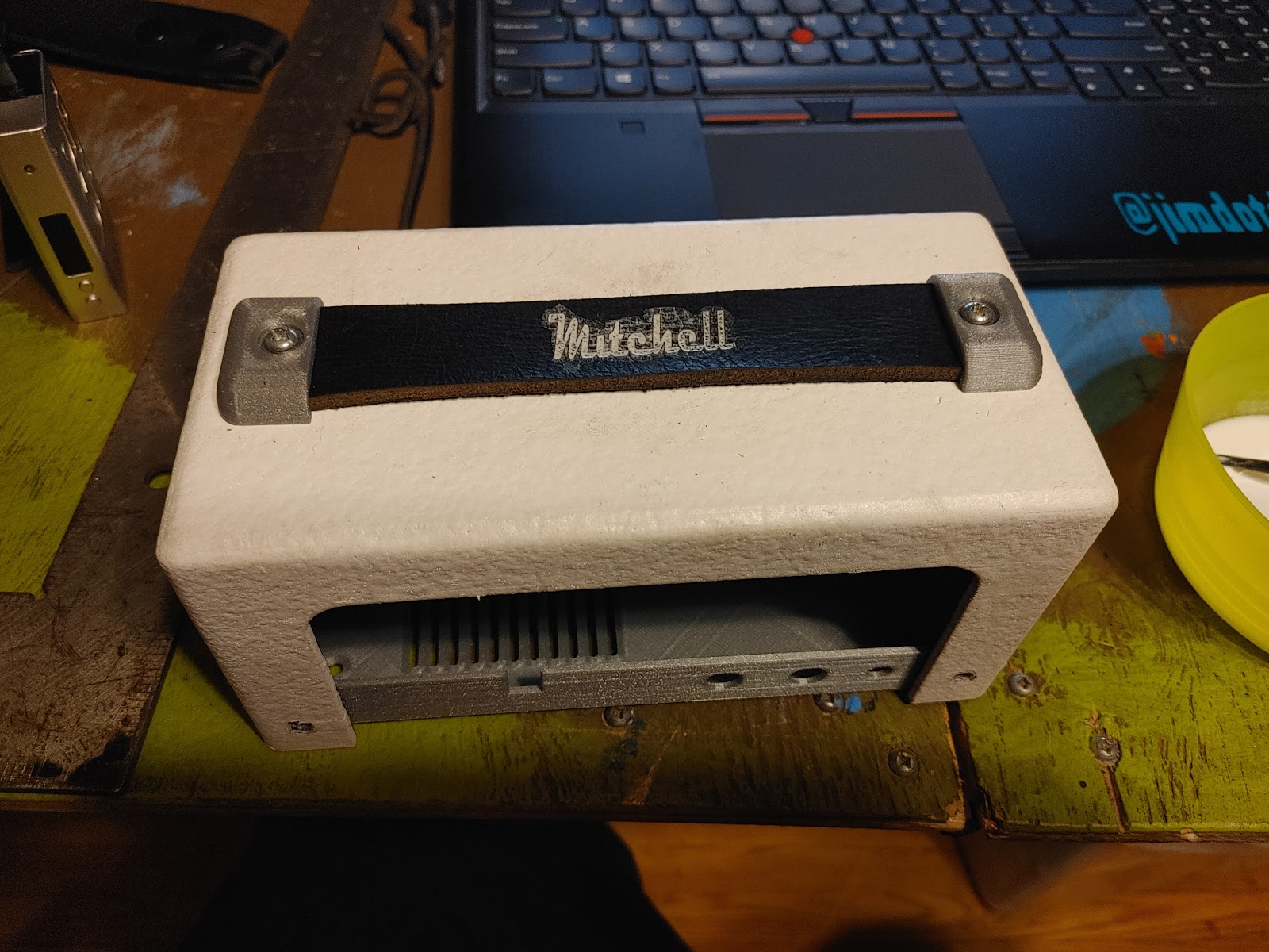
I was really liking the idea of it looking like a mini amp and felt confident it would fit off my measurements. I did worry that my crudely formed aluminum chassis would pose fitting issues, but it came out as expected.
Using some white Flexseal on the top cabinet to give it a textured rubbery feel similar to an amp head, then brushed inside black.
The aluminum chassis looked great, but in order to make it simpler for anyone who may be interested, I decided to design it for printing. In addition, I also installed the RCAs taking measurements to add a cut out with thin feature extrusion and some chamfering to increase the regidity.
For the handle I decided to use an old belt and make the width an inch for best use of material.
Once the handle pieces were printed and my old belt was cut to size, I finally had a use for a Neje Laser engraver a friend had given me. The software was easy enough to quickly figure out and after a few tests I centered up my leather and rand it for ten passes at 17ms per pass.
I mixed up some white acrylic paint with water and started washing some into the groove to stand out more.
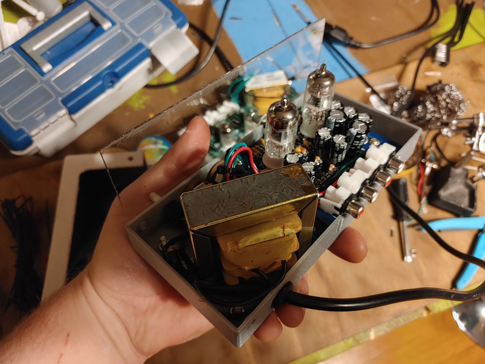
I believe everything to be complete at this point, so I wire up my toggle switch which is is a 6mm ON/OFF 125vac 10a toggle switch I found that came with a white sleeve between the power cord and primary coil on my transformer giving it a direct mains shut off.
Wiring the transformer straight to the board (or external power adapter) offers no true disconnect from mains. There is always power to the potentiometer, so it is ideal to add a switch.
The end result is truely pleasing. During the designing process, considerations were made to make it something easily reproducible with a total of eight printed parts, screws available from computers and a transformer with a seemingly common footprint and bolt pattern.
Because this turned out so well, I decide to make one for a friend of mine. When I ordered again, I didn't get sent the exact model of board. While the measurements were still the the same, the kid didn't Include standouts for the the board, so I made designed one to be included in the files.
Assembly went well for the both of them and everything fit snug.


Hi Jim, what i did, is to connect the output of the first valve into the input of de second one. When you increase de volume, probably you can overdrive de second valve. Unfortunatelly these valves don't produce a creamy sound like an 12ax7... It sound like a fuzz face.
ReplyDeleteI also put a preamp for the preamp 😁 I used a op amp, to be able to overdrive the first tube as well, since the guitar signal is too low.
Good luck with your project.
Ps. My amp does not sound like a marshall, but I am really happy with it.
Hey Juan, thanks for checking it out. I have completed this one and built another with a different version of the board and it all assemblies well.
ReplyDeleteI read elsewhere that you can remove the single 50k pot and add two pots separating the volume and gain. Right now I am looking forward to using this as a preamp to my interface, however; I have one more kit to "play" with and may elabarote more by adding a miniature cabinet to rest with it.
Thanks again!