James Mitchell

Hi, I'm James Mitchell

CIOS • Maker • Problem Solver

I build things, break things, and figure out how they work. JimDotDev is my public notebook for projects, experiments, lessons learned, and technical discoveries across making, computing, signals, research, and everyday problem solving.

Latest Articles

View all posts →

Printer upgrade - Bambu P2S AMS2

It's hard to believe it's been over 10 years since owning my first 3D printer.

It all started with a Vertex K8400. Like most printers at the time, it wasn't exactly plug and play, but it hooked me immediately. Before long I was building RepRap machines with welded steel frames that I fabricated myself, experimenting with Anet A8s, moving through CR-10s, spending years with the Artillery Sidewinder X1, and eventually adding SLA printing to the workshop.

If you've been in the hobby for a while, you'll know every printer had its own temperament.

Some fighting you every step of the way, others needing another upgrade before you even really get it out of the box.

Those machines taught me far more than how to print plastic. They pushed me into CAD and design, electronics, mechanics, firmware, and manufacturing. Before I knew it, what started as a hobby had become another tool that helped shape my career.

The Artillery X1 deserves a lot of credit. It has been an incredibly reliable machine for me and has produced a lot of great parts over the years, but after spending so much time in a continual tinker stage - I was wanting something more.

That's what brought me to the Bambu P2S with the AMS 2.

I'm still getting to know it, but so far it has felt less like setting up another machine and more like adding another tool to the workshop. The printer, AMS, Bambu Studio and MakerLab all fit together in a way that lets you spend less time figuring things out and more time making something. It basically configured itself.

MakerLab has also been useful tool I've overlooked. AI-assisted tools that can turn an image into a relief, generate printable models, or help someone bring an idea to life don't replace learning CAD—they simply make creating more accessible. This is something I am looking forward in seeing my family gain further involvement.

So far, pretty impressive machine!

Lowrider CNC Jackpot Controller

LowRider CNC - Finally Installing the Jackpot Controller

The Jackpot controller has been sitting on my bench for quite a while. My LowRider was already running reliably with an SKR board, so there wasn't much incentive to change it. With some free time, I finally decided it was time to make the move to FluidNC.

The first step was removing the existing SKR controller and documenting the wiring before disconnecting anything. Fortunately, the migration was straightforward. The only hardware changes required were replacing two connectors to match the Jackpot board. Once those were changed, the remaining wiring transferred over without much trouble.

With the controller installed, I powered everything up and connected to the Jackpot over Wi-Fi. After confirming communication, I reloaded my "config.yaml" configuration and started verifying each axis, endstop, and probe input. It's always worth taking the time to test each function individually before assuming everything is correct.

On the CAM side, I created a basic FluidNC post processor in Alphacam to get the machine moving. The initial version was intentionally simple—just enough to output clean G-code while I verified motion, probing, and general machine operation. As testing progresses, I'll continue adding the features I rely on in my normal workflow.

With the controller configured and the post processor producing usable code, it was time for the first test cuts. A few simple toolpaths confirmed that the machine was responding correctly, the coordinate system was behaving as expected, and the overall migration had been successful.

There is still work to do before I consider the conversion complete. I want to refine the Alphacam post, verify tool changes and probing routines, and spend some time cutting real projects before drawing any conclusions.

So far, though, the transition from the SKR board to the Jackpot controller has been much smoother than I expected. Hopefully these notes will help anyone else considering making the same upgrade.

Building a Cajón


I don't consider myself a woodworker, and I'm certainly not an instrument maker, but that didn't stop me from wondering if I could build a cajón from scratch.


The project started in SolidWorks, where I designed the enclosure before preparing the parts for my LowRider CNC in Alphacam. After sourcing a proper snare assembly, I spent time researching how different construction techniques influenced the sound, then experimented with a few ideas of my own.


One of the more interesting experiments was a magnetic snap-on ring for the rear sound hole. The idea was to quickly change the opening size and see how it affected the tone and resonance without permanently modifying the instrument.

This was very much a prototype, and looking back a year later I already have a list of improvements I'd make for Version 2. That said, it turned out better than I expected. I built it for a friend who's a percussionist, and hearing that it still rides around in his vehicle and gets played regularly is probably the best feedback I could ask for.

This sparked my interest in woodworking more and I have since acquired more tools to make these projects easier.

Laser burning


My Low Rider 2 doing some work for Christmas burning charcuterie and cutting boards.

It's been a while since I have played with it, but on these bamboo boards I have found a 600-900mm/m feed rate with a power of 30-40% power have been burning nice.


For weeks I have had in my mind that line from Ace Ventura "Laaaa-whoo-zaaa-heeer" with the idea to make "Cha-Cute-Ta-heer" for a charcuterie board for a family memeber whom I used to watch the movie basically on repeat when we were kids.

I found and purchased a design of Ace and modified it to suit the theme, adding the text.


The real pity is I assumed the boards were the same size, so it came out off center. Bummer! 

The kids have picked out something for their teachers:


Over all, it holds up well and for under 100 bucks at the time, the laser is holding up well!

Mini Virtual Pinball Machine


Laying in bed, I wondered what I could do with a couple old phones I had laying around and decided given the length of screen that a Pinball machine was going to be it, though I wasn't quite sure how. 

After searching, it's does seem there is a larger unit you can buy for your tablet and while I couldn't find info on it, it became apparent it was likely just a HID (human interface) compliant device.

I was looking for the best app for Pinball, and it seems the best is Zen Pinball. I hooked up a keyboard through a usb c adapter and confirmed it does have keyboard support. 


I had a Pro Micro in my drawer from playing with keystroke injection a while back, so I wired it up initially thinking four buttons only to discover that navigating the app required six.

Jurassic Park was one of the most iconic tables available on Zen Pinball, so it was the one I decided to make the focus point of the cabinet and found rough photos to give it some visual while designing.

One amazing detail utilizing an old phone for this project is the added vibration and tilt functions!


Increasing the games volume is going to be achieved with the 3w speaker seen below utilizing a 2 channel 3w amp.


War Magnetics


War Magnetics is a modular terrain set for table top war gaming specifically designed for 3D printing batch printing. The design incorporates magnets allowing host to expand piece by piece, creating a vast diverse gaming experience.

In some write up, I utilized "print more, for greater war" and established the term "Print.Click.Play" relative to the ability to print, click, play.. some assembly required, of course. 

The design of War Magnetics is done in such a way, it is very easy to adapt off of. Creating a new design tailored to " fantasy" or "sci-fi" is an easy task, with plans moving forward.


6J1 Tube Amp Case update

With a positive response to the design over the last week, I decided to purchase the other model of the 6J1 preamp to build for a friend while providing the opportunity to ensure it would fit smoothly in my case. 


Everything looks the same though this model seems a but scaled back with 35v caps over my firsts 50v.


Side by side, I believe the blue board wasn't cut to size as it has an additional 1/4 (give or take) on the PCB, but regardless these boards are physically similar.

Unfortunately the new board didnt come with the brass standouts as included in the last package, so I designed a standoff tray that can be printed. 


The tray works as expected and prints in a short amount of time.

Below is a complete run of parts totaling approximately 26 hours at .2 layer height.


Until I am able to finally get my Lowrider CNC up and running, I have found printing the dfx to scale makes a perfect stencil to achieve more accurate layout of the plexy glass.


Following through the rough draft of the instructions so far, I was able to quickly assembly the second one. 

Hoping to finish up the work this week by cleaning up some files and sharing on Thinkinverse.

6j1 Tube Preamp

I was browsing online for a soldering project for my oldest son for Christmas, when I came across this 6J1 Tube Preamp kit. It is intended for RCA, but I was hoping to play with adding 1/4" jacks to run my guitar through it.

What is a preamp? 

A preamp is an electrical device that takes a weak signal and amplifies it, making a weak signal stronger for further processing. Tube amps have always been said to have a warmer sound over solid-state.

The Build

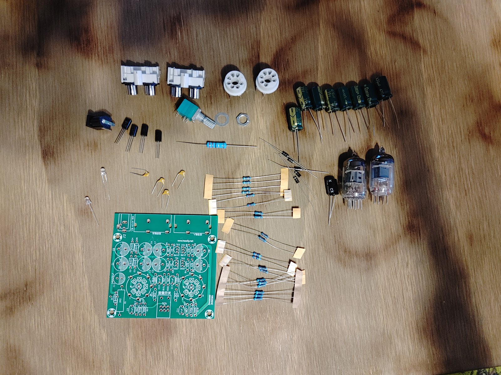
The kit comes with all the pieces tossed in a bag with no schematic, however; the board is clearly marked and all you really need to do is sort it all and organize your components. You can use a page like All About Circuit's resistor calculator to determine the Ohms by colour code bands, or you can switch your multimeter to Ohms and test manually - which is typically quicker.


Note: The board lists the 2.2k and 4.7k as "2k2" and "4k7" 


I tend start with all resistors as they are generally the lowest profiled components to be soldered - and while are not directional in anyway, I try to keep them in the same orientation across the board for quick refferencing if needing to troubleshoot later.


It's important to take note that the transistors are different pairs B647 - D667, and the locations respectively.


Above we can see the capacitors soldered in place


At this point I wasn't sure what I should use for a case. I just had to mount it to something, so I found a piece of aluminum that had some holes in it already and formed it to the shape I needed.


Once getting it to this point, I decided to draft it in SolidWorks to elaborate more on it.


I was really liking the idea of it looking like a mini amp and felt confident it would fit off my measurements. I did worry that my crudely formed aluminum chassis would pose fitting issues, but it came out as expected. 


Using some white Flexseal on the top cabinet to give it a textured rubbery feel similar to an amp head, then brushed inside black.


Prototyping off a scrape piece of aluminum has come a long way and designing all components in solidworks has allowed me elaborate more on the idea. 


The aluminum chassis looked great, but in order to make it simpler for anyone who may be interested, I decided to design it for printing. In addition, I also installed the RCAs taking measurements to add a cut out with thin feature extrusion and some chamfering to increase the regidity.

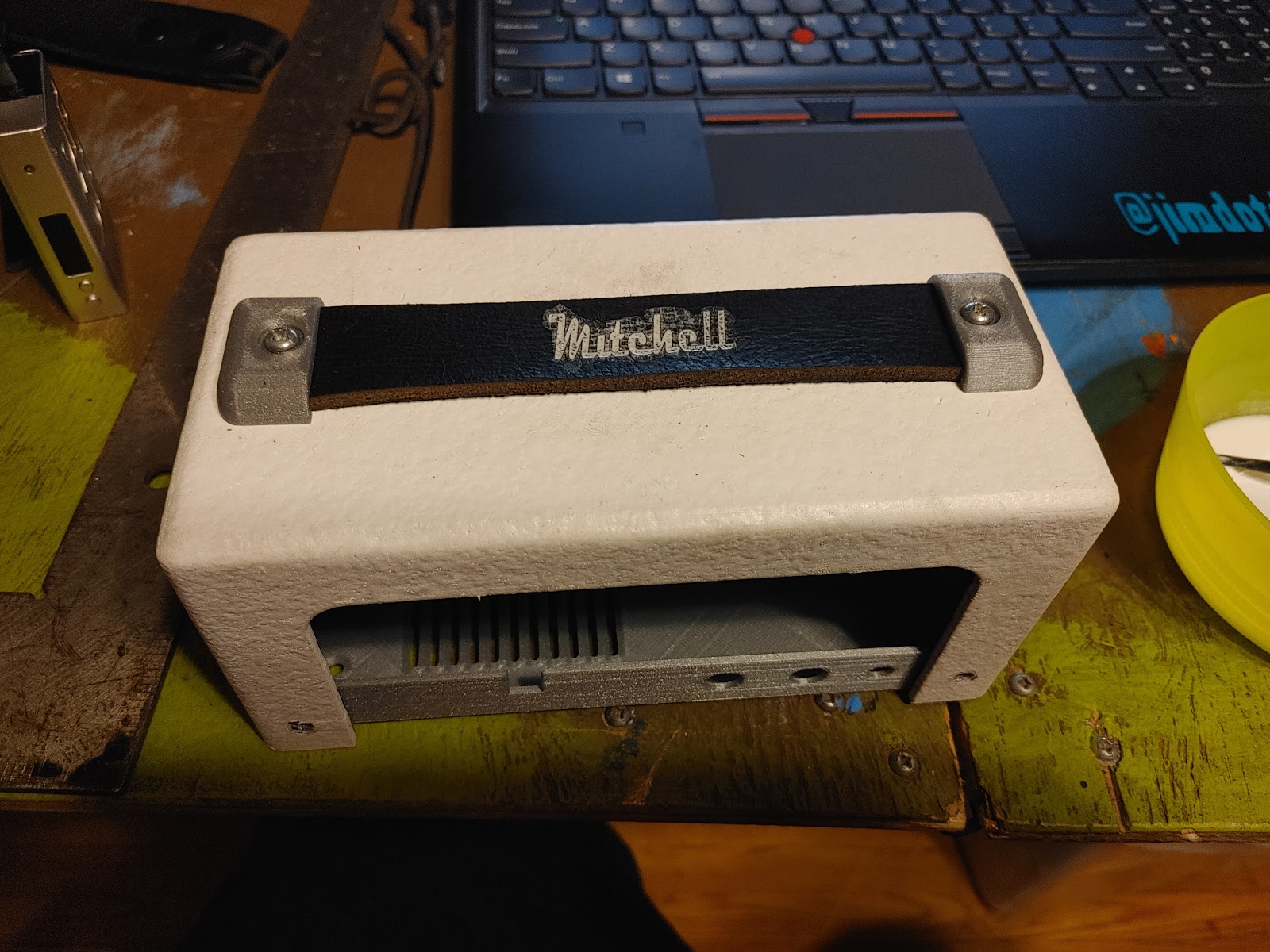
For the handle I decided to use an old belt and make the width an inch for best use of material. 


Once the handle pieces were printed and my old belt was cut to size, I finally had a use for a Neje Laser engraver a friend had given me. The software was easy enough to quickly figure out and after a few tests I centered up my leather and rand it for ten passes at 17ms per pass.

I mixed up some white acrylic paint with water and started washing some into the groove to stand out more.


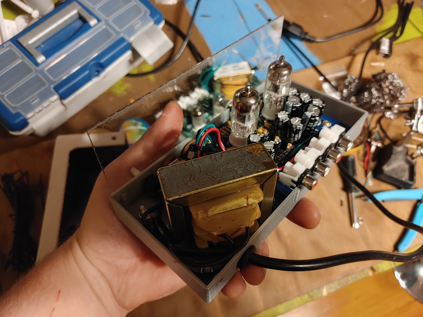
I believe everything to be complete at this point, so I wire up my toggle switch which is is a 6mm ON/OFF 125vac 10a toggle switch I found that came with a white sleeve between the power cord and primary coil on my transformer giving it a direct mains shut off.

Wiring the transformer straight to the board (or external power adapter) offers no true disconnect from mains. There is always power to the potentiometer, so it is ideal to add a switch.


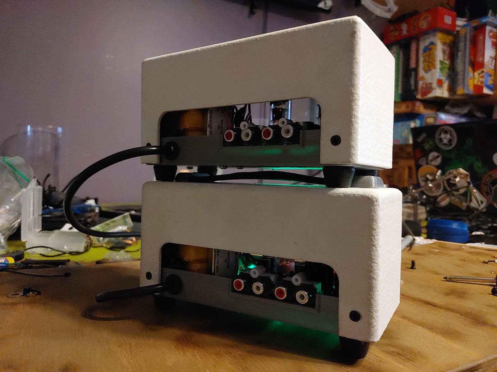
The end result is truely pleasing. During the designing process, considerations were made to make it something easily reproducible with a total of eight printed parts, screws available from computers and a transformer with a seemingly common footprint and bolt pattern.


Because this turned out so well, I decide to make one for a friend of mine. When I ordered again, I didn't get sent the exact model of board. While the measurements were still the the same, the kid didn't Include standouts for the the board, so I made designed one to be included in the files.


Assembly went well for the both of them and everything fit snug.


Over all it was a very fun project and the amp turned out awesome. The price point of preamps can be found for around 10 dollars and have so many various applications for projects like this.


Want the files? Email me!
RC Fun

Many people have asked me " what did you do over your Christmas holidays?" And my answer has been simple; " about a 15 pound gain and modified an RC car".

For Christmas I had picked up a couple carrera copper maxx RC cars from a local liquidation center. They are very sharp looking and after some research on them, they looked very identical to the wltoys a959 - which happens to be a well supported and affordable 1/18 scale RC car with lots of available hop ups and replacement parts.

After charging up the batteries we were blown away at how fast these cars were out of the box, and the boy did a super job keeping it under control. With the whether being fairly clear (up to +4 some days) we got out quiet a few times before it snowed again. 

With the car sitting for a few days I began to get antsy (hey, I'm on holidays) and took it out one night when it was clear at about 12:30am. I burned through two batteries and then smashed it off a curb blowing apart the front control arm. Once inside I discected the car and began to CAD one up to print.


As soon as I had it apart I started obsessing on how I could fit in a brushless motor with ESC, as brushless motors are more effient, lighter, and typically longer lasting than brushed motors - and I really just wanted a rediculous amount of power in this tiny little car.

Insight: https://en.m.wikipedia.org/wiki/Brushless_DC_electric_motor


I stripped everything out and took some measurements to do some part sourcing online and found this Surpass Hobby 45a waterproof ESC with a 4370kv motor and a very inexpensive Fly Sky RX TX 3ch controller. I knew right away that this was likely going to be too much torque for the current drivetrain and I would eventually have to upgrade them as well, but looking into the Wltoys a959B (the brushless version) it must have become an issue as there is a steel gearset already available.

First attempt at making a pick

Finding a banding material made of spring steel had me wanting to make my own pick. With the Sparrow Medusa being one of my favourites, I thought I would use it as a template to start.


The initial cut wasn't too bad. I made sure to leave lots of material to work with.


I then used a grinding bit and file to start making shape of the tip.


It's really starting to take shape here


At this point the tip is a bit long, but it works just as great as the original. I was really wanting to make it personable to me, so I started making a top hat in inspiration of Mad Hatter Labs.


At this point I was pretty happy with it. When originally starting with the banding it was .031 thick with coating, and I was able to bring it to .026 which allowed for clean movements.


After letting the paint dry I have been successful in picking and raking with this design.

About Me

James Mitchell

I'm James Mitchell, an IT Operations Specialist, builder, and lifelong learner. JimDotDev is where I document projects, experiments, lessons learned, and technical discoveries across fabrication, computing, RF systems, research, and practical problem solving.