James Mitchell

Hi, I'm James Mitchell

CIOS • Maker • Problem Solver

I build things, break things, and figure out how they work. JimDotDev is my public notebook for projects, experiments, lessons learned, and technical discoveries across making, computing, signals, research, and everyday problem solving.

Latest Articles

View all posts →

1978 Midway Space Invaders Cabinet

Found this 1978 Space Invaders cabinet online while doing one of my daily browse through on Kijiji and was quick to make a move on it. It seemed to be in great shape, but for being priced so low I wasn't very optimistic about see it run again - just figured I would use the cabinet with a Raspberry Pi.


Upon opening it up, we were quick to discover that the back service panel has a momentary switch with an outward position to lock it in the on position for servicing.


Once inside the parts seemed to be original all for what turned out to be the Braze Technologies Space Invaders Multi-card. The multi-card includes a POST self test aiding in troubleshooting, enable coinless free play and a variety of games that resemble space invaders, including Space Invaders Deluxe - and then, I caught it.

While looking over the CRT (cathode ray tube), two of the deflecting yoke wires were disconnected. The deflecting yoke is a type of magnetic lens used to focus or deflect the charged particles vertically and horizontally in the CRT monitor created by the electron beam, so with the horizontal leads disconnected would explain why there was this large vertical line on the monitor. Once testing after re-crimping the lead ends, I couldn't believe she was a live!


Now knowing it works, I took some time to clean it up and find a home for it. I tipped it over and fixed the front left leg, replaced the plug, and just took some time to observe how and what it all is.


I find after owning it for a few weeks now that I prefer Space Invaders Deluxe which fixed a few glitches, but also adds named score record to keep it competitive and fun for people to play.

While this game predates me, it was one that I still enjoyed and has been a cool project and fun to have around.

Diy Kijiji printer find

I managed to find this printer for a good deal to later identified it as a RepRap with an Arduino 2560 and ramps 1.4 extension.

The Arduino 2560 is a microcontroller, basically the "motherboard" with programmable input and outputs based on the atmega 1280 microchip. The Ramps 1.4 is a RepRap sheild that provides the circuitry in a package form needed for hotend, heatbeds, endstops and stepper drivers - the driver that handles the power and precise positioning. While the pairing is seen often in DIY kit printers, this combination is often common in similar "name brand" boards and clones as an all-in-one single integrated board.


After assessing the construction of the printer, the kit parts seemed poorly printed themselves leaving too much play, and I ultimately decided to start over.

The RepRap Wallace is discribed as basically a minimalist 3d printer. This using the least amount of materials, allowing for faster prototyping time and an overall simplified machine. It is with this I decided to convert the project, while making a few alterations along the way, to the RepRap Wallace.


And began printing


I printed the Wallace parts for 8mm threaded and machined rod at 15% infill and was happy with the turn out.


More printing was happening while I was assembling what I had and disassembling the remains of the purchased printer.


Now with the base and linear bearing mounts I am about 16 hours in for print time. The prints have come out great and everything is fitting up nicely - except for the carriage and vertical rods. Rather than cut the carriage rods, I took some measurments and began to create new mounts in solidworks.

At this time I am currently printing the hot end extruder assembly.


June 25 Update


Things have come a long way for the printer. I haven't been able to make as much progress as I would have liked over the passed week, however it is coming together.

Titobot - Uno bot!

My daughter has taken interest in programing through scratch. She enjoys creating storyboards through movements, text and sounds and all that scratch has to offer.

Relating and making the connection to her from movements based on time, events or other functions to that of the physical attributions of robotics has struck interest in her, which is why I started looking for a base to work off of.

I found Ottobot, which is an open-source project that I didn't have all the parts for. Looking further, I found what I would almost call the designers first version called Tito.

I had everything needed for Tito from the Arduino Tito to the servos and mini breadboard.

All that was left to do was print.


While I have a bit more assembly, I think this will be a great project for her and myself as we work together to promote her growth in understanding of programing and mechanics.

Stay tuned!

AMD fx8150 glass build

This is a PC that has evolved over time which belongs to friend. While a bit older now, the 8150 holds strong to gaming and was a great chip for budget build.


PLC Training

I have purchased an online PLC training course including 24 hours of video that I am working hard on completing.To aid in my training, I wanted to create a trainer that would give me the basics needs while physically having some hardware to wire up.

A trainer of any type should have basic input components such as NC (normally closed) NO (normally open) variation of toggle/push button switches and maybe a inductive proximity to start. These can normally be easily accessible and don't break the bank.

Output possibilities for me at this time include pneumatic actuators, streppers and a variation of relays. However, for the most part, desktop training will include mostly indicators.

While I originally went bigger with the
I/O, I ended up with this;


Located in the top right corner of my rack, you can see my arduino rail mounted. Communicating between the arduino and PLC is something I have pondered about since my introduction to the industrial PLC and programmable relays.


Looking at it stripped, I basically made a simple H frame using 1.5 x 1/4 angel, drilled and tapped, added some DIN for rail mounting, and drilled a total of six holes for grounds.

No measurement was really set in stone, I just went with what fit around the plc I'm already own.

The Photobooth


A photo booth holds this nostalgia even in a world where everyone has a high resolution camera in their pocket capable of 16MP photos, people are still amused by a photobooth. It's just, awesome!

We wanted to capture that feeling at our wedding and provide guests with a cool and fun way to leave memories and take something home with them at the end of the night. We looked around but everything was costly and bland looking, so I set off with the plan to make one and this a is blog post on how it started.

The build

I took an older HP Pavilion laptop with a touch screen that was donated to me and completely stripped it apart. This was a great machine to its owner and it is a perfect machine for this build with quad core processor and 8 GB of DDR3.


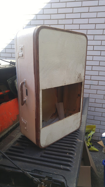
I was given an old brief case from my sister who has an eye for old unique pieces and it just so happens it will fit the screen!


To mount the screen I made a rough frame out of wood glued inside the case. I then used a double side adhesive and later secured it with aluminum duct tape as well.

I had a few comments about "taping" the screen into place and although I wasn't very keen on it either, it really is how cellphones and tablets are held together and hasn't been an issue yet.


Once the screen was in place and the laptop apart, I made a frame out of as scrap wood and aluminum with standouts to mount the motherboard to a frame. I then made use of the 2.5 inch drive tray that was in the laptop and fastened it the side with some wood screws.


The 2x6 wood I had was helpful in giving support for the brief case while providing beefy material to attach the mount for the tripod stand.


I searched for software that would provide the functionality I was looking for while providing the best user experience and found that in a very affordable application called Instant Photobooth.

Instant Photobooth was very simple to setup with a ton of cool features. I ended up using it with a feature in Windows with call Kiosk mode. Basically, when the photobooth is fired up it boots straight into a user account that is restricted to launching anything but Instant Photobooth.

At this point it looked great, had character but needed a camera and some finishing touches.

I hummed and hawed about what camera to install. There are a lot of great cameras with a very nice Sony lense supported by the software, however budget was still a concern. I ended up settling with the quality and autobalancing features of a Logitech web cam and mounted it the same way as the screen.

The face of it still needed a special touch, so I cut a picture frame I found at a local crafts store to frame it off with drapes on the side the same colour as the original software background.

To throw off where the lense was, I added two rubbies from the dollar as a final touch.


Once we started playing with it, we decided it needed a printer. I purchased a Cannon Selphy cp1200 for 119 bucks, made a mount and cut hole in the side of the case. I was very impressed by the quality and print time accomplished with this printer, approximately 45 - 60 seconds in total.


I have been very pleased with the outcome of project and it has received very positive feed back everywhere it's been so far. While at this point has full functionality, I have a few ideas to make improvements in the near future.

Mini Desktop Conveyor


Mini Desktop Conveyor

One of the projects I developed to demonstrate my rapid prototyping capabilities was this desktop conveyor system. Rather than focusing on a single manufacturing process, the objective was to showcase how design, fabrication, electronics, and automation can be combined into a functional prototype in a relatively short development cycle.

The conveyor was designed  in SolidWorks, with many of the structural components produced through additive manufacturing. Other mechanical components were fabricated and assembled to create a compact, fully functional conveyor capable of supporting small automation demonstrations.

To introduce an element of industrial automation, the conveyor was equipped with an inductive proximity sensor to detect workpieces and stage an automated process. This allowed the system to simulate how sensors are commonly integrated into manufacturing equipment for part detection, sequencing, and process control.

Projects like this are an excellent example of how modern prototyping extends beyond simply creating a mechanical assembly. They require an understanding of CAD design, fabrication methods, electronics, sensors, and automation, bringing together multiple disciplines to rapidly develop and validate functional concepts before moving toward production.


About Me

James Mitchell

I'm James Mitchell, an IT Operations Specialist, builder, and lifelong learner. JimDotDev is where I document projects, experiments, lessons learned, and technical discoveries across fabrication, computing, RF systems, research, and practical problem solving.